Post by: DaveVA78Chieftain on August 13, 2009, 11:15 PM
http://www.mediafire.com/?sharekey=e1bbeecabe8041c8d5a101cf914073b4f0385774821355a5 (http://www.mediafire.com/?sharekey=e1bbeecabe8041c8d5a101cf914073b4f0385774821355a5)
(https://www.classicwinnebagos.com/forum/proxy.php?request=http%3A%2F%2Fi286.photobucket.com%2Falbums%2Fll120%2FBaileyDave%2FWinnebago%2FMopar%2520Ignition%2FSlide04.gif&hash=6c2654b668211e3bf584783e4239a075bf019872)
Components
The Chrysler Electronic Ignition System consists of a special pulse-sending distributor, an electronic control unit, a two-element ballast resistor, and special ignition coil. The distributor does not contain breaker points or a condenser, these parts are replaced by a reluctor and magnetic pick-up unit. The system was introduced into the MH chassis in 1973 and replaced the breaker points system. It was used from then on in all Dodge Class A motorhomes (M300-M600)
Ballast Resistor
| (https://www.classicwinnebagos.com/forum/proxy.php?request=http%3A%2F%2Fi286.photobucket.com%2Falbums%2Fll120%2FBaileyDave%2FWinnebago%2FMopar%2520Ignition%2FBallast.jpg&hash=0657676e69b2196ccd16499fd34f2bb7690d0f50) |
| Coil Develops the high voltage required for the spark plugs. | (https://www.classicwinnebagos.com/forum/proxy.php?request=http%3A%2F%2Fi286.photobucket.com%2Falbums%2Fll120%2FBaileyDave%2FWinnebago%2FMopar%2520Ignition%2FCoil.jpg&hash=f195072791acd546561b8d85b24bcb7eb20f752f) |
| Distributor Provides firing control pulse to ECM Provides Mechanical Advance Provides Vacuum Advance (Controled by carburator vacuum) Routes high Voltage pulse from Coil to proper spark plug (https://www.classicwinnebagos.com/forum/proxy.php?request=http%3A%2F%2Fi286.photobucket.com%2Falbums%2Fll120%2FBaileyDave%2FWinnebago%2FMopar%2520Ignition%2FPUCoil.jpg&hash=f3807d506e14aea982eeebed456e825e02d7adce) | (https://www.classicwinnebagos.com/forum/proxy.php?request=http%3A%2F%2Fi286.photobucket.com%2Falbums%2Fll120%2FBaileyDave%2FWinnebago%2FMopar%2520Ignition%2FDistributor.gif&hash=a807d7cdc141b723d76c6003fc2ab4b6095b2acd) |
| Electronic Control Module (ECM) Power Amplifier that controls primary coil voltage. Determines the length of high voltage pulse. CAUTION Disconnecting the plug from the ECM with the Ignition key ON can damage the ECM module. | (https://www.classicwinnebagos.com/forum/proxy.php?request=http%3A%2F%2Fi286.photobucket.com%2Falbums%2Fll120%2FBaileyDave%2FWinnebago%2FMopar%2520Ignition%2FECM.jpg&hash=c58a38a8c9b8827cfc82529c8ae1b0f2b67c7b11) |
(https://www.classicwinnebagos.com/forum/proxy.php?request=http%3A%2F%2Fi286.photobucket.com%2Falbums%2Fll120%2FBaileyDave%2FWinnebago%2FMopar%2520Ignition%2FECMHarness.jpg&hash=6e35c335c5b6f9c49de50f1eac30e264dae93c1a)
(https://www.classicwinnebagos.com/forum/proxy.php?request=http%3A%2F%2Fi286.photobucket.com%2Falbums%2Fll120%2FBaileyDave%2FWinnebago%2FMopar%2520Ignition%2FECMPlate.jpg&hash=e368c90ab3340a340602871ef018c1ae67c6949d)
Operation
(https://www.classicwinnebagos.com/forum/proxy.php?request=http%3A%2F%2Fi286.photobucket.com%2Falbums%2Fll120%2FBaileyDave%2FWinnebago%2FMopar%2520Ignition%2FIgnFunc.jpg&hash=abacdf2428c6feb6ccc7b323b51488ffeeabe0aa)
The ignition primary circuit is connected from the battery to the ignition switch (I1) to the primary side of the ignition coil to the control unit (pin 2) where it is grounded.
The secondary circuit is the same as in conventional ignition systems: Secondary side of the coil to the coil wire to the distributor cap to the rotor back out the distributor cap to the spark plug wires to the spark plugs.
The distributor provides a firing control pulse to the control unit. As the distributor shaft rotates, the reluctor turns past the pick-up sensor. When a reluctor tooth passes near the pick-up unit, a small voltage is induced into the magnetic pick-up sensor. This voltage pulse is sent to the ignition control unit signaling the control unit to interrupt the ignition primary circuit.
This causes the magnetic field in the primary side of the coil to collapse which results in a high voltage pulse in the secondary side of the coil providing the required voltage to fire the spark plugs.
The advantages of this system are:
- The transitors in the control unit can make and break the primary ignition circuit much faster than conventional ignition points
- A higher primary voltage can be utilized since this system can be made to handle higher voltage without adverse effects, whereas ignition breaker points cannot.
- The quicker switching time of this system allows longer coil primary circuit saturation time and longer induction time when the primary circuit collapses. This increased time allows the primary circuit to build up more current and the secondary circuit to discharge more current.
- Initial Timing Advance setting
- Mecanical Advance
- Vacuum Advance
Initial Timing Advance setting
This is the reference point upon which all engine timing is based. Timing advance is required because it takes time to burn the air-fuel mixture. Igniting the mixture before the piston reaches top dead center (TDC) will allow the mixture to fully burn soon after the piston reaches TDC. If the air-fuel mixture is ignited at the correct time, maximum pressure in the cylinder will occur sometime after the piston reaches TDC allowing the ignited mixture to push the piston down the cylinder with the greatest force. If the ignition spark occurs at a position that is too advanced relative to piston position, the rapidly expanding air-fuel mixture can actually push against the piston still moving up, causing detonation and lost power. If the spark occurs too retarded relative to the piston position, maximum cylinder pressure will occur after the piston is already traveling too far down the cylinder. This results in lost power, high emissions, and unburned fuel.
1973 (Electronic Ignition)
318 - 2.5 +/- 2.5 Degress BTDC
413 - 5.0 +/- 2.5 Degress BTDC
440 - 7.5 +/- 2.5 Degress BTDC
1974 and later
Typically the same as 1973 but refer to the Emissions Label on the Valve Cover.
Note: Seeing the timing marks and reference plate on a 440-3 can be difficult. You normally have to turn the front wheels to the left and get up inside the right front wheel well to see the timing marks. Even then, you may have to unbolt the radiator overflow container and move it out of your way to see the timing marks.
440-3 Timing tab mounted on timing cover:
(https://www.classicwinnebagos.com/forum/proxy.php?request=http%3A%2F%2Fi286.photobucket.com%2Falbums%2Fll120%2FBaileyDave%2FWinnebago%2F440%2520Timing%2520Cover%2F4027560.jpg&hash=598f98bfc61820fa14305ebd2c37ee6f6482c921)
Location of timing tab on front of engine (360 tab is located on drivers side of water pump):
(https://www.classicwinnebagos.com/forum/proxy.php?request=http%3A%2F%2Fi286.photobucket.com%2Falbums%2Fll120%2FBaileyDave%2FWinnebago%2F440Front-1.jpg&hash=91a317605c235bd7eafc6352487d01e3af619393)
Close up of a 440-3 Timing tab aligned with timing marl on harmonic balancer:
(https://www.classicwinnebagos.com/forum/proxy.php?request=http%3A%2F%2Fi286.photobucket.com%2Falbums%2Fll120%2FBaileyDave%2FWinnebago%2FMopar%2520Ignition%2F100_0362.jpg&hash=d76b39e899ee5ae28297b82288e96a5b51a7d51a)
Rotor position with #1 cylinder at TDC on compression stroke (pointing at alternator):
(https://www.classicwinnebagos.com/forum/proxy.php?request=http%3A%2F%2Fi286.photobucket.com%2Falbums%2Fll120%2FBaileyDave%2FWinnebago%2FMopar%2520Ignition%2F100_0366.jpg&hash=e80b2e4e60fbf3c348c33d360e5625121e9cd24f)
Relationship of #1 plug wire (white tape) to distributor cap hold down clamp:
(https://www.classicwinnebagos.com/forum/proxy.php?request=http%3A%2F%2Fi286.photobucket.com%2Falbums%2Fll120%2FBaileyDave%2FWinnebago%2FMopar%2520Ignition%2F100_0364.jpg&hash=40b6c501559e667fe57d901489f498df3a7feca4)
79 and later 440-3 timing tab:
(https://www.classicwinnebagos.com/forum/proxy.php?request=http%3A%2F%2Fi286.photobucket.com%2Falbums%2Fll120%2FBaileyDave%2F78timingMark.jpg&hash=f13c2c967c8130b372e6f9b0c4e616ad24b574fb)
360 timing tab:
(https://www.classicwinnebagos.com/forum/proxy.php?request=http%3A%2F%2Fi286.photobucket.com%2Falbums%2Fll120%2FBaileyDave%2F360TimingTab.jpg&hash=b125b5b35efa78f3ba547eaba2ee9e6e54d78b4d)
Mecanical Advance
Ignition timing has to become increasingly advanced (relative to TDC) as the engine speed increases so that the air-fuel mixture has the correct amount of time to fully burn. As the engine speed increases, the time available to burn the mixture decreases but the burning itself proceeds at the same speed, it needs to be started increasingly earlier to complete in time. An increasing mechanical advancement of the timing takes place with increasing engine speed. This is possible by using the law of inertia. Weights and springs inside the distributor rotate and affect the timing advance according to engine speed by altering the angular position of the timing sensor shaft with respect to the actual engine position. This type of timing advance is also referred to as centrifugal timing advance. The amount of mechanical advance is dependent solely on the speed at which the distributor is rotating.
Vacuum Advance
The second method used to advance the ignition timing is called vacuum timing advance. It increases fuel economy and driveability, particularly at lean mixtures. A vacuum chamber on the side of the distributor automatically varies the instant at which the spark occurs as a function of manifold vacuum. Vacuum advance provides the additional advance that is needed when the engine is operating at part throttle. At part throttle less air-fuel mixture gets into the cylinders and the mixture takes longer to burn after it is ignited. Because the mixture burns more slowly, the piston will be past top dead center and moving down before the mixture has a chance to burn and produce high power. As a result much of the power in the fuel will be lost. The vacuum advance mechanism consists of a flexible spring-loaded diaphragm connected by a linkage to a plate on which the magnetic pick-up is mounted (breaker plate on which the points are mounted for non-electronic ignition systems). The sealed side of the diaphragm is connected by a tube to the carburetor . The throttle valve (butterfly) is below the vacuum passage (port) in the carburetor air horn so there is no vacuum advance when the engine is idling because the throttle is closed. However, when the throttle is partly open, intake manifold vacuum pulls the diaphragm in and this causes the breaker plate to rotate a few degrees and advance the timing . With wide-open throttle there is very little vacuum in the intake manifold so there will be no vacuum advance. In most instances the vacuum advance is disconnected before checking the timing and point gap (non-electronic ignition systems). In summary:
- No Vacuum Advance at idle.
- No Vacuum Advance at wide open throttle.
- Vacuum Advance system is intended for emissions control, driveability, and fuel economy.
Vacuum advance plate action:
(https://www.classicwinnebagos.com/forum/proxy.php?request=http%3A%2F%2Fi286.photobucket.com%2Falbums%2Fll120%2FBaileyDave%2FWinnebago%2FMopar%2520Ignition%2FVacuumAdvance.gif&hash=4cec0183df26041173a641d31a8386a1527ed0c1)
In response to emission control requirements, in 1974 Dodge added a emission control sytem which senses engine temperature in order to regulate the vacuum advance system when the engine is hot or cold. This system increases the advance when the engine is cold by allowing engine manifold vacuum to also be used when the engine is cold. Once the engine is warmed up, normal ported vacuum is used. At low temperature the advance allows the enriched warm-up mixture to burn more completely, providing better and cleaner cold-engine running.
Firing Order
For all engines 1-8-4-3-6-5-7-2
Left side cylinders are numbered (from front) 1-3-5-7
Right side cylinders are numbered (from front) 2-4-6-8
Firing order diagram fro 440-3 engine:
(https://www.classicwinnebagos.com/forum/proxy.php?request=http%3A%2F%2Fi286.photobucket.com%2Falbums%2Fll120%2FBaileyDave%2FWinnebago%2FMopar%2520Ignition%2F440firingorder.jpg&hash=9ffc11d833338cf07a42c3f8a3e4723ead491e12)
Start vs Run
- Start
When the ignition key is placed in the START position, battery voltage is supplied to both the I1 and I2 leads.
The I1 lead provides voltage to the AUX side (5.0 Ohm) of the Ballast Resistor and to pin 1 (primary power input) of the ECM. The output of the AUX resistor is applied to ECM pin 3 and is used for electronic circuit stablization.
The I2 lead provides voltage to the output side of the Compensating Resistor (0.5 Ohm) section of the Ballast Resistor therfore the Compensating Resistor is bypassed during starting.
Full battery supply voltage is then applied to the plus (+) side of the Coil. The minus (-) side of the coil is connected to pin 2 of the ECM. The ECM (via pin 2) controls electrical current flow through the coil. Electrical current will flow through the coil until the the distributor pick-up (ECM pins 4 and 5) signals it is time to fire the spark plug. The ECM then shuts OFF the current flow which causes the magnetic field in the coil to collasp. This results in a high voltage pulse being routed to the spark plug via the coil wire, distributor cap, rotor and spark plug wire. After a predetermined amount of time (designed into the ECM circuitry) the ECM will turn the current back ON to the coil. - RUN
When the ignition key is placed in the RUN position, voltage is supplied to just the I1 lead.
The I1 lead provides voltage to the AUX side (5.0 Ohm) and the Compensating side (0.5 Ohm) of the Ballast Resistor and to pin 1 of the ECM. Since there is no voltage from the igniition switch on I2, the voltage (reduced) applied to the coil is via the Compensating Resistor. The remaning operation is identical to the START position.CAUTION
Bypassing (jumpering around) the Compensating Resistor for extended periods of time will damage the ECM.
Carry a spare Ballast Resistor in your on-board toolkit instead.
Notes:
- The Ballast Resistor is a high failure item. Most people carry a spare Ballst Resistor with them
- Corroded wiring connectors and solder joints will reduce voltage to the ignition circuitry resulting in hard starting and phantom problems. In the wiring harness drawing above, take note of the location of the Major Solder Junction reference as it is the main distribution point for ignition and charging circuitry.
You can see by this drawing of a 1973 chassis, there are many connections and solder joints between the battery and the Ballast Resistor/ECM Module. Corrosion, overstressed wiring (high current), and age all factor in resulting in voltage drops. The in-line fusible links located at the starter relay weaken with time due to current draw.
(https://www.classicwinnebagos.com/forum/proxy.php?request=http%3A%2F%2Fi286.photobucket.com%2Falbums%2Fll120%2FBaileyDave%2FWinnebago%2FMopar%2520Ignition%2F73BatSupplyd.jpg&hash=8a1a394bbf04f4420170ca9546c8a0516d66d843) - For reference, basic operation of the Multiple Spark Discahrge (MSD) system is based on the same principles as the MOPAR system. Hookup is a little different (no ballast resistor) and the MSD fires a spark plug multiple times but the system is still triggered by a pick-up sensor and controls current flow through the coil. The deference is that it turns the coil off and on multiple times for each firing pulse.
- Useful Tools
- Actron CP7677 Auto Troubleshooter
(https://www.classicwinnebagos.com/forum/proxy.php?request=http%3A%2F%2Fi286.photobucket.com%2Falbums%2Fll120%2FBaileyDave%2FWinnebago%2FMopar%2520Ignition%2FActronCP7677.jpg&hash=47b5bf393710696042dfe2c57cfa88cdb619cdfd)- Tests engine RPM and dwell
- Measures AC/DC voltage, DC current and resistance
- Tests continuity, wiring and diodes
- Tests starting & charging, ignition and fuel delivery systems
- Actron CP9087 Ignition Module and Sensor Testor
(https://www.classicwinnebagos.com/forum/proxy.php?request=http%3A%2F%2Fi286.photobucket.com%2Falbums%2Fll120%2FBaileyDave%2FWinnebago%2FMopar%2520Ignition%2FActronCP9087.jpg&hash=33fa34aa86c58ceba3295496076bb8693eb4e7a0)- Test ignition modules and igniters
- Tests sensors including O2, MAP, MAF, knock and crankshaft sensors (ie: Distributor pickup sensor)
- Tests continuity, wiring and diodes
Allows you to check the ECM (Section 3 using the Magnetic Reluctance Pick-up hookup on page 3-9 of the tester manual).
Allows you to check the Distributor Pick-up sensor (Section 2, page 2-46 of the tester manual, Magnetic Reluctance version)
- Actron CP7677 Auto Troubleshooter
(https://www.classicwinnebagos.com/forum/proxy.php?request=http%3A%2F%2Fi286.photobucket.com%2Falbums%2Fll120%2FBaileyDave%2FWinnebago%2FMopar%2520Ignition%2FTSIgnSchematic.jpg&hash=68eed9359aaf836b40a0c044b9f8c788b61c1e6f)
A voltmeter with a 20,000 ohm/volt rating and a 1 1/2 volt battery powered ohmmeter are required.
Battery voltage must be at least 12 volts.
IS RETURNED TO RUN POSITION
| No voltage at plus (+) terminal of coil when ignition key is in RUN position. Note The fact that the engine tries to start (fires) when the ignition key is in START position indicates that the Distributor, ECM and coil are working. It also means battery voltage is being applied to the input side of the Ballast resistor and ECM pin 1. Verify 12VDC on input side of Ballast Compensating Resistor (Connector with 2 red wires). Replace Ballast resistor. Compensating Resistor resistance value - 0.5 to 0.6 ohms | (https://www.classicwinnebagos.com/forum/proxy.php?request=http%3A%2F%2Fi286.photobucket.com%2Falbums%2Fll120%2FBaileyDave%2FWinnebago%2FMopar%2520Ignition%2FI2BallastIn.jpg&hash=60e4563e8bc905827c4502baa23d806ba1057272) |
IN EITHER START OR RUN POSITION
Make sure the ignition switch is off when removing or replacing the control unit connector.
Disconnecting the plug from the ECM with the Ignition key ON can damage the ECM module.
| 1. Turn Ignition Switch OFF. 2. Remove wiring plug from the Control Unit (ECM). 3. Ground negative voltmeter lead. 4. Connect voltmeter positive lead to the harness connector cavity No. 1. 5. Turn Ignition Switch to RUN. 6. Verify voltage is within 1 volt of battery voltage with all accessories off. If correct voltage is present, go to step 36 (problem in wiring path to battery from ECM pin 1) otherwise continue to next step. | (https://www.classicwinnebagos.com/forum/proxy.php?request=http%3A%2F%2Fi286.photobucket.com%2Falbums%2Fll120%2FBaileyDave%2FWinnebago%2FMopar%2520Ignition%2FCavity01a.jpg&hash=a3d3b28ba272883113509cec0cf9904637371791) |
| 7. Connect voltmeter positive lead to the harness connector cavity No. 2. Note With connector removed from ECM there is no current following in the circuit. In this condition, there will not be a voltage drop across the Ballast Compensating Resistor therfore reading a voltage value within 1 volt of battery votage is normal. 8. Verify voltage is within 1 volt of battery voltage with all accessories off. If correct voltage is present, go to step 16. (coil and compensating resistor OK) otherwise continue to next step. | (https://www.classicwinnebagos.com/forum/proxy.php?request=http%3A%2F%2Fi286.photobucket.com%2Falbums%2Fll120%2FBaileyDave%2FWinnebago%2FMopar%2520Ignition%2FCavity02a.jpg&hash=895b84966ebda85bf2fa58bba449e63edde10459) |
| 9. Connect voltmeter positive lead to plus (+) side of coil (Pink wire from Ballast Resistor). 10. Verify voltage is within 1 volt of battery voltage with all accessories off. If voltage is incorrect, go to step 13. (Ballast Resistor circuit problem) otherwise continue to next step. 11. Coil is bad, improperly grounded, or wiring between coil and ECM Pin 2 is defective. 12. Turn Ignition Switch OFF and repair. Coil Primary - 1.4 to 1.8 Ohms (plus {+} to minus {-}) Coil Secondary - 8K to 12K Ohms (Center to case ground) | (https://www.classicwinnebagos.com/forum/proxy.php?request=http%3A%2F%2Fi286.photobucket.com%2Falbums%2Fll120%2FBaileyDave%2FWinnebago%2FMopar%2520Ignition%2FI2Ballast.jpg&hash=240fd222d8a27a2a9dd9f789bc2440d4a6e682c9) |
| 13. Connect voltmeter positive lead to input side of Ballast 0.5 Ohm Compensating Resistor (side with 2 pink wires at one end {output}; red wire on other end {input}). 14. Verify voltage is within 1 volt of battery voltage with all accessories off. 15. Turn Ignition Switch OFF. If voltage is correct, either ballast resistor is defective (0.5 Ohm Compensating Resistor) or wiring between Ballast Resistor and coil is defective. If voltage incorrect, wiring between ballast resistor and Ignition switch is defective. Repair wiring. | (https://www.classicwinnebagos.com/forum/proxy.php?request=http%3A%2F%2Fi286.photobucket.com%2Falbums%2Fll120%2FBaileyDave%2FWinnebago%2FMopar%2520Ignition%2FI2BallastIn.jpg&hash=60e4563e8bc905827c4502baa23d806ba1057272) |
| 16. Connect voltmeter positive lead to the harness connector cavity No. 3. Note With connector removed from ECM there is no current following in the circuit. In this condition, there will not be a voltage drop across the Ballast Compensating Resistor therfore reading a voltage value within 1 volt of battery votage is normal. 17. Verify voltage is within 1 volt of battery voltage with all accessories off. If correct voltage is present, go to step 21 (AUX resistor OK) otherwise continue to next step. | (https://www.classicwinnebagos.com/forum/proxy.php?request=http%3A%2F%2Fi286.photobucket.com%2Falbums%2Fll120%2FBaileyDave%2FWinnebago%2FMopar%2520Ignition%2FCavity03a.jpg&hash=36056bea2b997fbf436be36ffe6ccfe30a457e49) |
| 18. Connect voltmeter positive lead to input side of Ballast 5.0 Ohm Auxilary Resistor (side with dark green wire at one end {output}; red wire on other end {input}). 19. Verify voltage is within 1 volt of battery voltage with all accessories off. 20. Turn Ignition Switch OFF. If voltage is correct, either ballast resistor is defective (5.0 Ohm Aux Resistor) or wiring between Ballast Resistor and ECM pin 3 is defective. If voltage incorrect, wiring between ballast resistor and Ignition switch is defective. Repair wiring. | (https://www.classicwinnebagos.com/forum/proxy.php?request=http%3A%2F%2Fi286.photobucket.com%2Falbums%2Fll120%2FBaileyDave%2FWinnebago%2FMopar%2520Ignition%2FI2BallastIn.jpg&hash=60e4563e8bc905827c4502baa23d806ba1057272) |
| 21. Turn Ignition Switch OFF. 22. Connect one multimeter lead to the harness connector cavity No. 4 and the other multimeter lead to the harness connector cavity No. 5 23. Set Multimeter to read Resistance (Ohms) 24. Verify Distributor Pick-up Sensor resistnace is between 350 to 550 Ohms. If resistance is correct, go to step 28 (1st Distributor Pick-up Sensor check OK) otherwise continue to next step. | (https://www.classicwinnebagos.com/forum/proxy.php?request=http%3A%2F%2Fi286.photobucket.com%2Falbums%2Fll120%2FBaileyDave%2FWinnebago%2FMopar%2520Ignition%2FCavity04-05a.jpg&hash=1eba2ede6cb6053bd0b78b67daffa60e0f3ac0cb) |
| 25. Unplug the Pick-up Sensor (lead from Distributor). . 26. On the Pick-up sensor distributor lead, connect one multimeter lead to one pin in the plug and the other multimeter lead to the other pin in the plug 27. Verify Distributor Pick-up Sensor resistnace is between 350 to 550 Ohms. If resistance is correct, the wiring from the ECM plug to the distributor plug is defective. Repair wiring. If the resistance is incorrect, replace Distributor Pick-up Sensor Note If you have a Actron CP9087 Ignition Module and Sensor Testor, perform Sensor Test (Section 2, page 2-46 of the tester manual, Magnetic Reluctance version) | (https://www.classicwinnebagos.com/forum/proxy.php?request=http%3A%2F%2Fi286.photobucket.com%2Falbums%2Fll120%2FBaileyDave%2FWinnebago%2FMopar%2520Ignition%2FPickupCoila.jpg&hash=72eb95fec583e6ad63367c6e78eee68cc5ae7940) |
| 28. Connect one multimeter lead to the harness connector cavity No. 4 and the other multimeter lead to a good ground. 29. Verify there is no continuity (open circuit; maximum resistance). If there is no continuity, go to step 31 (2nd Distributor Pick-up Sensor check OK) otherwise continue to next step. 30. Distributor Pick-up Sensor is shorted to ground. Replace Distributor Pick-up Sensor. | (https://www.classicwinnebagos.com/forum/proxy.php?request=http%3A%2F%2Fi286.photobucket.com%2Falbums%2Fll120%2FBaileyDave%2FWinnebago%2FMopar%2520Ignition%2FCavity04a.jpg&hash=8e073fbe1458ba98449aad450ed6ebfdd6eca30a) |
Note The following test is performed on the ECM module itself, not the plug/harness. 31. Connect one multimeter lead to the ECM pin 5 and the other multimeter lead to a good ground. 32. Verify there is continuity. If there is continuity, go to step 34 (ECM Ground check OK) otherwise continue to next step. 33. Tighten bolts holding ECM module to mounting plate. Retry steps 31 and 32. If there is now continuity, got to next step, otherwise replace ECM module. 34. Reinstall wiring plug to Control Unit (ECM). 35. All components and wiring to the ECM module have been verified to be working correctly. If there is still no spark to the plugs then the problem is one or more of the following:
| (https://www.classicwinnebagos.com/forum/proxy.php?request=http%3A%2F%2Fi286.photobucket.com%2Falbums%2Fll120%2FBaileyDave%2FWinnebago%2FMopar%2520Ignition%2FECMGround.jpg&hash=b32ed2660c972917d931de0236c02b48a87da6c9) (https://www.classicwinnebagos.com/forum/proxy.php?request=http%3A%2F%2Fi286.photobucket.com%2Falbums%2Fll120%2FBaileyDave%2FWinnebago%2FMopar%2520Ignition%2FAirGap.jpg&hash=844494784b3afab305e63c00e356c89218987d0c) |
| 36. Turn Ignition Switch OFF. 37. Using the appropriate drawing below, back track down the battery supply circuit to locate the bad connection (broken or corroded as applicable). | |
(https://www.classicwinnebagos.com/forum/proxy.php?request=http%3A%2F%2Fi286.photobucket.com%2Falbums%2Fll120%2FBaileyDave%2FWinnebago%2FMopar%2520Ignition%2F73BatSupplyd.jpg&hash=8a1a394bbf04f4420170ca9546c8a0516d66d843)
(https://www.classicwinnebagos.com/forum/proxy.php?request=http%3A%2F%2Fi286.photobucket.com%2Falbums%2Fll120%2FBaileyDave%2FWinnebago%2FMopar%2520Ignition%2F74BatSupplyd.jpg&hash=1c3780bae3e54db89568848c4970c547ff95384a)
(https://www.classicwinnebagos.com/forum/proxy.php?request=http%3A%2F%2Fi286.photobucket.com%2Falbums%2Fll120%2FBaileyDave%2FWinnebago%2FMopar%2520Ignition%2F75BatSupplyd.jpg&hash=8101eb294aabc8f7a1e371deb61eda7000e7524d)
Ignition switch Quick reference:
Note: Wires in manual are identified by circuit name, wire gauge and color
BATT-12BK: Circuit = BATT; 12 gauge wire; BK = Black wire color.
Use that info to confirm your on the correct wire.
(https://www.classicwinnebagos.com/forum/proxy.php?request=http%3A%2F%2Fi286.photobucket.com%2Falbums%2Fll120%2FBaileyDave%2F79UpM3-M4IgnitionSwich.jpg&hash=19c9b8451f1732bb5e3b4b9fd1127d36eab1dc0b)
1. At bottom area of steering column you will see a half moon connector that connects to the ignition switch
2. At the connector:
A. Make sure 12VDC is always available to the BATT-12BK wire. Nothing on this wire means neither ignition nor starter will not work via key.
B. With Key ON - Make sure you have 12VDC on IGN1-16RE wire (Ignition supply; 16 gauge; red wire) and ACC-12LB (accessory; 12 gauge; Light Blue). IGN1-16RE supplies the ballast resistor, ignition module, and voltage regulator.
C. With key in START - make sure you have 12VDC to START-18OR and IGN2-14PK. The START-18OR wire supplies the 12VDC control signal to starter solinoid so the starter will engage. The IGN2-14PK signal goes to + side of coil during start to bypass the ballast resistor. Provides full 12VDC for easier starts.
Example of ignition switch connector that has a bad conductor (red wire).
(https://www.classicwinnebagos.com/forum/proxy.php?request=http%3A%2F%2Fi286.photobucket.com%2Falbums%2Fll120%2FBaileyDave%2FWinnebago%2FMopar%2520Ignition%2F100_0369.jpg&hash=85ce89b25ea5de74b7d147b7595fd81d31572cd3)
Post by: tomr on August 14, 2009, 06:44 AM
Post by: JDxeper on August 14, 2009, 04:28 PM
Post by: DaveVA78Chieftain on March 15, 2010, 10:09 AM
The Lost Art of Maintaining a Mopar Distributor
Reformated and updated article:
Hemming Motor News Article - Hemmings Muscle Machines - JANUARY 1, 2007 - BY RAY T. BOHACZ
Back in the day when every spark ignition engine was equipped with breaker points, it was hard enough to find someone who really knew what they were doing when it came to working on a distributor. Today that quest is almost impossible. But if you own a muscle car that was produced prior to 1975, with only a few exceptions, the coil is fired through breakers. Thus, it would behoove those owners to become familiar with the proper service procedures for breaker point ignition systems. This installment of "The Lost Art" series will focus on the Chrysler breaker point and electronic ignition distributor. This style of distributor was used from the early 1960s until the last carburetor-equipped V-8 was delivered from a Mother Mopar assembly line.
Back to basics
An ignition system has two basic circuits. The primary, which consists of the breaker points, condenser, ignition switch, and primary windings of the ignition coil. The secondary part of the ignition system includes the secondary windings of the coil, the distributor rotor and cap, along with the spark plug wires and the spark plugs.
The ignition coil can be considered a transformer because it takes the 12 volts supplied by the battery and raises it up to around 30,000 volts. This is required so that the electricity can bridge the gap of the spark plug under cylinder pressure.
The breaker points control the flow of current through the ignition coil and allow the field to build. It can be considered a very accurate on/off switch. When the breakers are closed, the ignition coil is charging (dwell period). When they break open, the field in the coil collapses and induces the higher secondary voltage. On the average V-8 engine the breaker points open and close approximately 150 times per second at 60 mph. Under those conditions the points are closed for around 0.005 of a second for each spark plug firing.
In that brief interval, current has flowed through the coil primary, building up a powerful magnetic field. As the points separate, the primary current tries to keep flowing and arc across the opening contacts. The condenser, however, being connected directly across the primary circuit, absorbs the electrical energy at the breaker, accomplishing two things. First, the points are protected against arcing. Second, the energy stored in the condenser "kicks back" and helps in the almost instantaneous breakdown of the magnetic field in the coil.
If the breaker points are in poor condition, a diminished spark output from the coil will be the result. Points in good condition have a light frosty-gray color. If the points are black after a few thousand miles, it indicates that oil or grease has gotten on them. An excessive amount of oil on the distributor cam may be the cause of this condition and can result from a faulty breather or PCV system, causing the oil to come up through the distributor-shaft bushing.
If, under inspection, the points have deep pits and craters, the condenser usually is defective or has failed. When the crater is developing in the ground point (the stationary side) the condenser does not have sufficient capacity. When the crater is on the point connected to the moving arm, the condenser has excessive capacity. The moving member is the positive side while the stationary member is the negative side.
A faulty condenser or excessive charging output voltage is responsible for excessive wear of the electrical contacts. Wear of the rubbing block will cause the length of time the contacts are closed to increase and will result in gradually retarding the ignition timing. In contrast, if the point contact surface erodes from excessive current flow, the ignition timing will advance.
Properly installed points always have the outside diameters registering so that contact is made at approximately the center.
Point alignment is something that is very important and is often overlooked during installation. Proper alignment can be accomplished by bending the stationary contact and never by bending the moving arm between the rubbing block and the contact. Alignment of the fiber block of the moving arm with the cam is accomplished by bending the arm between the hinge pin and the block. The fiber block should never be filed or sandpapered.
Breaker point spring tension adjustment is critical, but will almost be impossible to check today unless you can find an old application specific spring tension gauge. For a Mopar, the breaker point spring tension should be set at 20 ounces. This value will reduce as the rubbing block wears. Adjustment to the spring tension is accomplished by moving the end of the spring either forward or backward under the screw, which fastens the free end to the breaker base plate. Excessive tension will create a high rate of wear at the rubbing block, but allow high rpm. Too little tension will cause point bounce and poor performance at high engine rpm.
The only way to properly service a Chrysler distributor, or any other brand that has the mechanism under the breaker plate, is to remove it from the engine (Delco distributors had the weights under the rotor). Trying to do a proper job with the distributor in the engine is impossible since all of components that require service cannot be accessed. So follow along as HMM shows you "The Lost Art" of Mopar distributor maintenance!
| Procedure | Both Points and Electronic Distributor Types | |
|---|---|---|
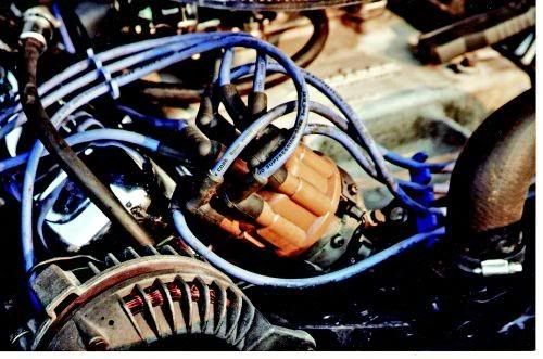
| Since the distributor is going to need to be removed from the engine, the timing marks will need to be cleaned and highlighted with either chalk or white paint. | 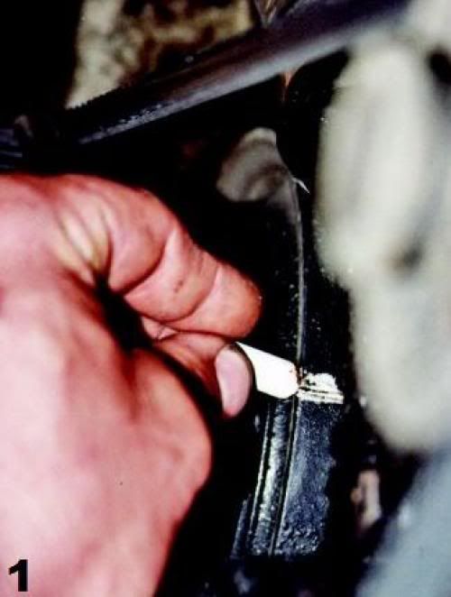 | |
| If you are not familiar with the current distributor setting you should check the timing before removing the distributor. This way you will have a reference to go back to after you are done. Whenever using a timing light, always look directly at the timing plate and mark, not at an angle. If viewed at an angle, parallax error will occur. This means a false reading will be taken. The best example of parallax error is viewing the speedometer or gas gauge from the passenger seat. What is seen is not accurate. If you do not own a timing light and are going to purchase one, a dial-back or advance light is the best choice. This tool allows for easy plotting of the advance curve, though it is more expensive than a base light. | 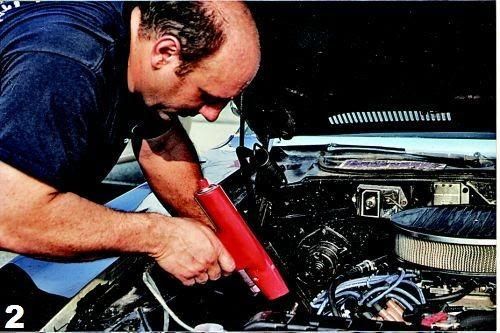 | |
| Remove the distributor cap and identify the position of the rotor. You can tap the starter around to place the rotor at a good reference, such as a bolt or bracket. Mopar V-8 distributors (small and big block) use a slot at the bottom of the shaft, so they can only be installed two ways, correct and 180 degrees out. Slant-Six distributors have a gear that meshes directly with the cam and can be installed incorrectly very easily. Also remember to mark or identify the clock position of the case so the engine starts easily before final adjustment. | 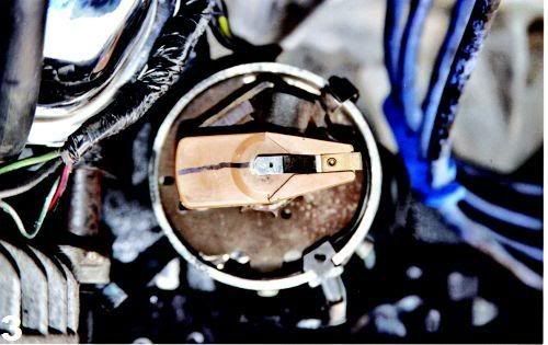 | |
| All Mopars use a ballast resistor. Our subject car, owned by Kurt Mesmer, is a 1973 'Cuda with a 1967 383 and electronic ignition. The purpose of the ballast resistor is to reduce the running voltage to the points, or with electronic systems, to the control box. The engine cranks on full battery power; when the ignition key is released to the "Run" position, the current feeds through the resistor. Chrysler used two styles of ballast resistors; a single, or a double (as shown here). If the ballast is defective the engine will start, but stall as soon as the key is released to the "Run" position. | 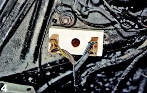 | |
| Procedure | Points Distributor | Electronic Distributor |
| If your car is using a Mopar electronic ignition system it will have a transistor box under the hood, usually on the firewall or inner fender. Mopar Performance (the old Direct Connection) sells a very nice kit for older breaker point Mopars to convert to true Chrysler electronic ignition. Many muscle cars have had this installation done over the years and is widely accepted as being correct and not considered a modification. | 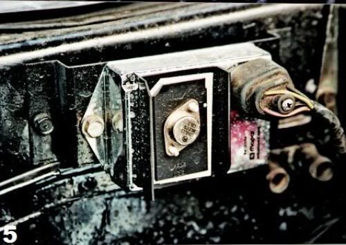 | |
| With the distributor removed the components are in plain view. Our subject had an old set of Standard Ignition Products "Blue Streak" brand points. They are identified by the blue plastic on the arm and the auxiliary lubrication wick. The condenser attaches to the breaker plate with a screw. The wire that goes from the coil negative to the breakers is called a "pig tail" and is designed for a specific resistance. | 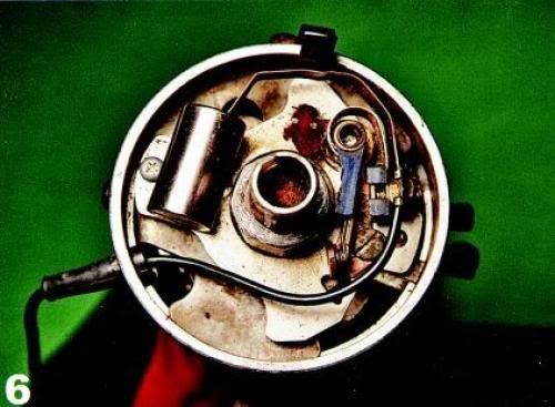 | |
| The Mopar electronic distributor replaces the distributor cam with a reluctor and a magnetic pick-up. | 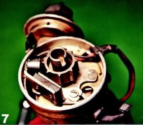 | |
| Procedure | Both Points and Electronic Distributor Types | |
| Since the distributor is going to come completely apart, it is a good idea to check the vacuum advance canister for its integrity. A handheld vacuum pump will show if the diaphragm holds vacuum. If it is defective or hardly moves the breaker plate, now is the time to install a new one. The author suggests moving up to an adjustable vacuum advance canister that is offered by most performance ignition suppliers. | 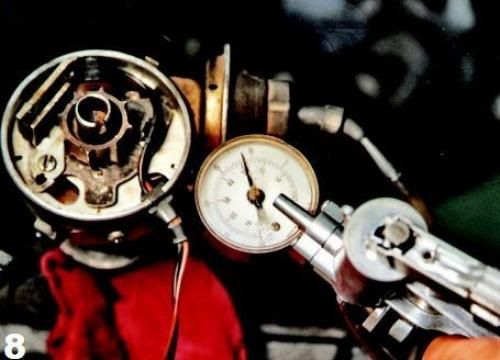 | |
| Procedure | Points Distributor | Electronic Distributor |
| The first step is to remove the breaker points and condenser. After removal, examine the contacts to determine the wear using the drawing in the next caption. Contact alignment is critical to proper performance. Were the breakers that you just removed aligned properly? | 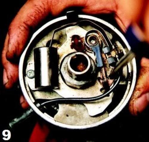 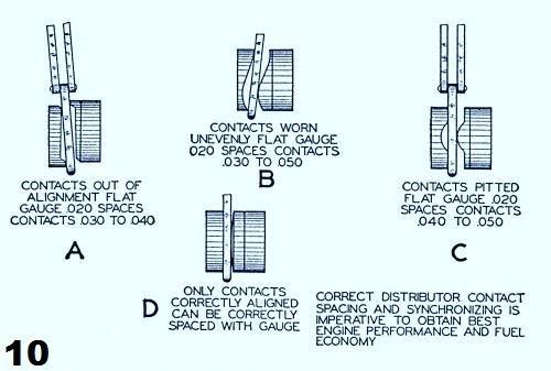 | |
| On electronic designs, the reluctor needs to be pried off with two screw- drivers. There is a small roll pin that registers the reluctor in the proper place while holding it secure. DO NOT LOSE THIS PIN! | 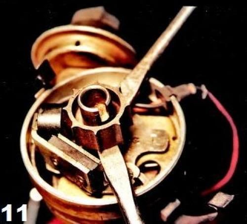 | |
| Procedure | Both Points and Electronic Distributor Types | |
| After removing the vacuum advance attaching screws, the canister can be slid out from the breaker plate. You may need to pry apart the breaker plate slightly to get the arm and locating point loose. | 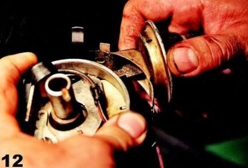 | |
| Procedure | Points Distributor | Electronic Distributor |
| Remove the 2 breaker/reluctor plate screws on the side of the distributor and remove the plate. With the breaker/reluctor plate removed this is what you will see on both the point and electronic distributors. The centrifugal weights reside under the stop mechanism which is attached to the shaft. | 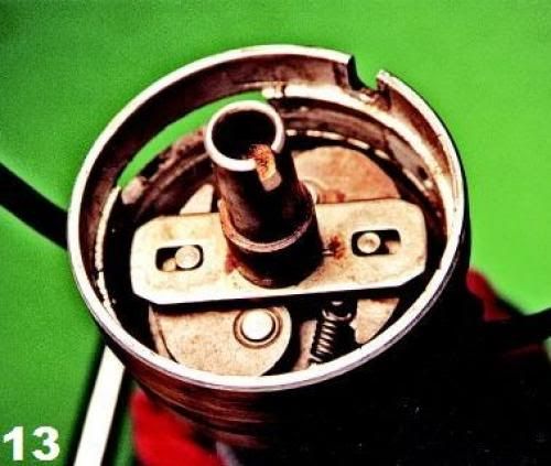 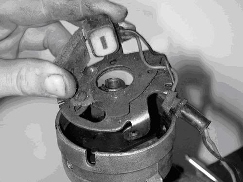 | |
| Procedure | Both Points and Electronic Distributor Types | |
| Turn the breaker/reluctor plate over and slide the slotted spring steel clip to the large hole to separate the two parts of the plate. |  | |
| Inspect and clean the breaker/reluctor plate halves. Check for any scoring. Often the incorrect point or condenser hold-down screw is used that is too long and scores or binds the plate. This results in the vacuum advance not working properly. Lubricate the slide bushings with a high-temperature grease. | 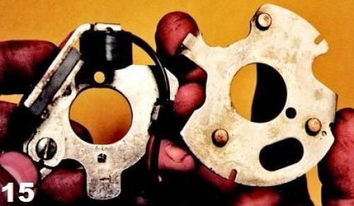 | |
| To access the centrifugal weights the oil wick needs to be lifted out of place. | 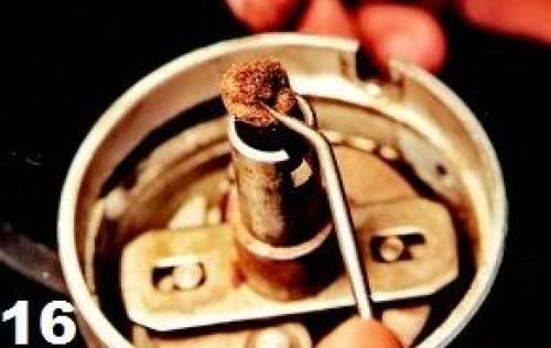 | |
| A snap ring holds the stop to the distributor shaft. Usually it can be removed with either two very small screwdrivers or a combination of an awl and a screwdriver. This ring is frustrating to remove, so be patient. You will hardly ever get it out on the first try! Don't lose the removed ring. | 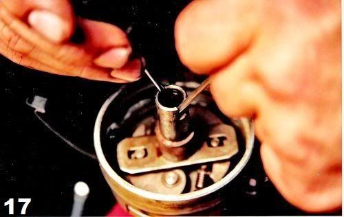 | |
| With the weights removed, clean and inspect the shaft, bushing and pivot points. If any rust is present, use either a fine Scotch-Brite pad or light emery cloth to clean it off. Lubricate the pivot points with the same grease that was used on the breaker plate slides. Check the shaft for side-to-side freeplay. There should be no more than 0.008 inch of free play. If the play is excessive the distributor bushings in the case are worn and need to be rebuilt or a new casting purchased. | 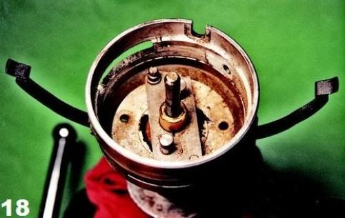 | |
| Inspect and clean the weights and springs. If you ever wanted to install a high performance advance kit, now is the time. Factory ignition parts are always of the highest quality and are worth the few extra dollars if you can still find them. | 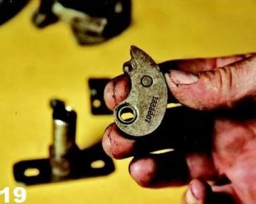 | |
| Procedure | Points Distributor | Electronic Distributor |
| Reverse the steps to assemble the distributor. With the new points installed, set the cam so that it is on the rubbing block. This will have the points fully open. Turn the shaft and watch the points open and close. Check the alignment and adjust if necessary. Place the rubbing block on the cam and using the proper specification, adjust the point gap using a feeler gauge. The gauge needs to be installed straight and the contacts should be rubbing slightly on each side when adjusted properly. Secure the screw when done. Turn the distributor and re-check the gap. | 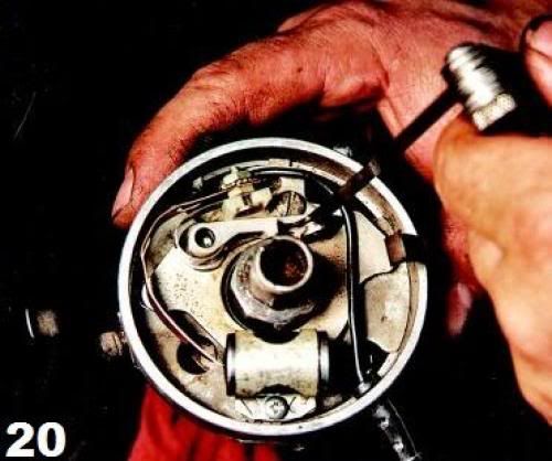 | |
| It's essential that the proper distributor cam lube is applied or the rubbing block will wear prematurely. Place a small amount on only one lobe. Then turn the distributor shaft quickly by hand to spread it to the other lobes. Carefully wipe any excess off the side of the rubbing block. Some brands of breaker points supply a small capsule of cam lube, or you can buy a tube from a better auto parts store, such as NAPA. The tube shown in the picture belongs to the author and is about 25 years old! |  | |
| The Mopar electronic distributor has a reluctor gap. A special non-metallic feeler gauge (brass) is required. Set the gap between one lobe of the reluctor and the magnet. Most models used 0.008 inch, but reference a shop manual for the specification for your application. If the reluctor gap is set too wide, hard starting may occur due to a weak output signal. | 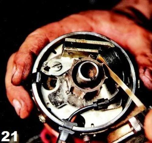 | |
| Procedure | Both Points and Electronic Distributor Types | |
| The final and most important step is to moisten the center wick with engine oil. You want the wick wet, but not saturated with oil so that it flies out into the distributor cap. This oil lubricates the top shaft bushing and is essential for long service life. Do not forget to also check the distributor gear for wear. Install the distributor and set the ignition timing. Your Mopar will now run like never before. | 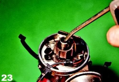 | |
Post by: DaveVA78Chieftain on March 15, 2010, 10:23 AM
<HTML>
<HEAD>
<TITLE>MOPAR Distributor Specifications</TITLE>
</HEAD>
<BODY BGCOLOR="#FFFFFF" TEXT="#000000" LINK="#FF0000" VLINK="#800000" ALINK="#FF00FF" BACKGROUND="?">
Dodge Motorhome Ignition Specifications
| 318-3 | 1969-1971 Points Distributor Point Gap.014"-.019" Dwell 30º - 35º 5º ± 2.5º BTDC F-10 Champion - .035" Gap Firing Order 1-8-4-3-6-5-7-2 | Centrifugal Advance | |
| (Dist Degrees @ Dist RPM) 0.5º to 3.5º @ 500 RPM 7.0º to 9.0º @ 950 RPM 15.0º to 17.0º @ 2250 RPM | Crankshaft Degrees @ Crankshaft RPM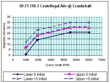 | ||
| Vacuum Advance | |||
| (Dist Degrees @ Inches of Mercury) 1.0º to 4.5º @ 9.5" 10.5º to 13.5º @ 15.0" | Crankshaft Degrees @ Inches of Mercury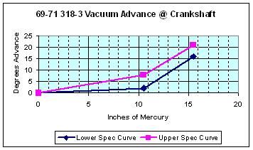 | ||
| 318-3 | 1972 Points Distributor Point Gap.014"-.019" Dwell 30º - 35º 5º ± 2.5º BTDC F-10 Champion - .035" Gap Firing Order 1-8-4-3-6-5-7-2 | Centrifugal Advance | |
| (Dist Degrees @ Dist RPM) 0.5º to 4.0º @ 550 RPM 7.0º to 9.0º @ 900 RPM 14.0º to 16.0º @ 2200 RPM | Crankshaft Degrees @ Crankshaft RPM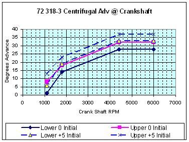 | ||
| Vacuum Advance | |||
| (Dist Degrees @ Inches of Mercury) 2.0º to 4.0º @ 10.0" 8.0º to 10.5º @ 15.0" | Crankshaft Degrees @ Inches of Mercury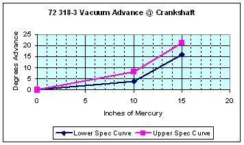 | ||
| 318-3 | 1973 Electronic Distributor Reluctor Gap.008" 2.5º ± 2.5º BTDC F-10 Champion - .035" Gap Firing Order 1-8-4-3-6-5-7-2 | Centrifugal Advance | |
| (Dist Degrees @ Dist RPM) 0.0º to 2.0º @ 500 RPM 6.5º to 9.0º @ 850 RPM 13.5º to 15.5º @ 2150 RPM | Crankshaft Degrees @ Crankshaft RPM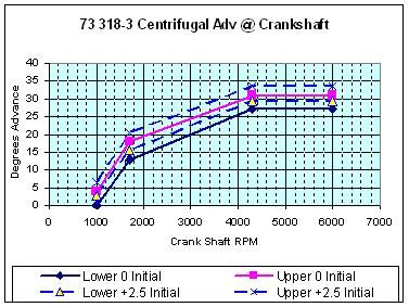 | ||
| Vacuum Advance | |||
| (Dist Degrees @ Inches of Mercury) 1.0º to 3.5º @ 9.5" 7.0º to 10.0º @ 14.0" | Crankshaft Degrees @ Inches of Mercury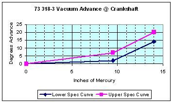 | ||
| 318-3 | 1974-1977 Electronic Distributor Reluctor Gap.008" Emissions Lable (2.5º ± 2.5º BTDC) F-10 Champion - .035" Gap Firing Order 1-8-4-3-6-5-7-2 | Centrifugal Advance | |
| (Dist Degrees @ Dist RPM) 0.0º to 2.0º @ 500 RPM 6.5º to 9.0º @ 850 RPM 13.5º to 15.5º @ 2150 RPM | Crankshaft Degrees @ Crankshaft RPM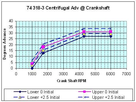 | ||
| Vacuum Advance | |||
| (Dist Degrees @ Inches of Mercury) 1.0º to 3.5º @ 9.5" 7.0º to 10.0º @ 14.0" | Crankshaft Degrees @ Inches of Mercury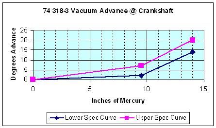 | ||
| 413-1 | 1969-1971 Points Distributor Point Gap.013"-.018" Dwell 28º - 32º 5º ± 2.5º BTDC N-6 Champion - .035" Gap Firing Order 1-8-4-3-6-5-7-2 | Centrifugal Advance | |
| (Dist Degrees @ Dist RPM) 0.5º to 3.5º @ 500 RPM 8.5º to 10.5º @ 1000 RPM 12.5º to 14.5º @ 2000 RPM | Crankshaft Degrees @ Crankshaft RPM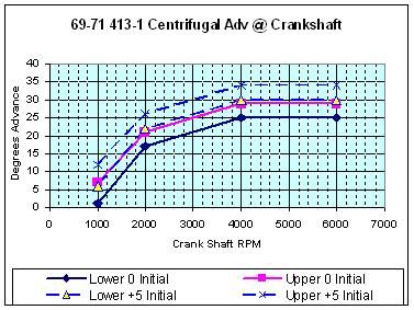 | ||
| Vacuum Advance | |||
| (Dist Degrees @ Inches of Mercury) 1.0º to 4.0º @ 7.5" 8.5º to 11.5º @ 12.0" | Crankshaft Degrees @ Inches of Mercury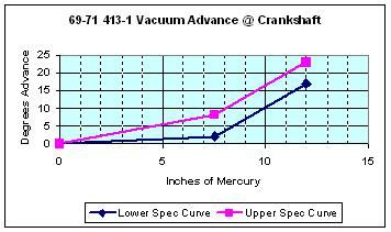 | ||
| 413-1 | 1972 Points Distributor Point Gap.013"-.018" Dwell 28º - 32º 5º ± 2.5º BTDC N-6 Champion - .035" Gap Firing Order 1-8-4-3-6-5-7-2 | Centrifugal Advance | |
| (Dist Degrees @ Dist RPM) 0.5º to 4.0º @ 550 RPM 8.0º to 10.0º @ 900 RPM 12.0º to 14.0º @ 2000 RPM | Crankshaft Degrees @ Crankshaft RPM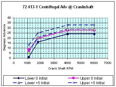 | ||
| Vacuum Advance | |||
| (Dist Degrees @ Inches of Mercury) 0.5º to 3.5º @ 7.0" 8.5º to 11.5º @ 12.0" | Crankshaft Degrees @ Inches of Mercury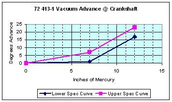 | ||
| 413-1 | 1973 Federal Electronic Distributor Reluctor Gap.008" 5.0º ± 2.5º BTDC N-6 Champion - .035" Gap Firing Order 1-8-4-3-6-5-7-2 | Centrifugal Advance | |
| (Dist Degrees @ Dist RPM) 1.0º to 3.5º @ 550 RPM 8.0º to 10.5º @ 900 RPM 11.5º to 14.0º @ 1900 RPM | Crankshaft Degrees @ Crankshaft RPM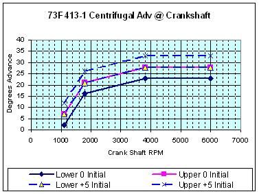 | ||
| Vacuum Advance | |||
| (Dist Degrees @ Inches of Mercury) 1.0º to 4.5º @ 7.5" 7.5º to 10.5º @ 13.5" | Crankshaft Degrees @ Inches of Mercury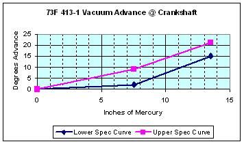 | ||
| 413-1 | 1973 California Electronic Distributor Reluctor Gap.008" 5.0º ± 2.5º BTDC N-6 Champion - .035" Gap Firing Order 1-8-4-3-6-5-7-2 | Centrifugal Advance | |
| (Dist Degrees @ Dist RPM) 1.0º to 4.0º @ 550 RPM 6.0º to 8.0º @ 800 RPM 11.5º to 13.5º @ 1900 RPM | Crankshaft Degrees @ Crankshaft RPM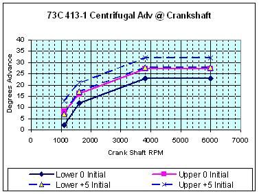 | ||
| Vacuum Advance | |||
| (Dist Degrees @ Inches of Mercury) 0.5º to 4.0º @ 9.5" 6.5º to 9.5º @ 13.5" | Crankshaft Degrees @ Inches of Mercury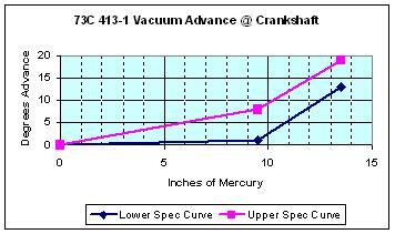 | ||
| 440-3 | 1973 Electronic Distributor Reluctor Gap.008" 7.5º ± 2.5º BTDC BL-9Y Champion - .035" Gap Firing Order 1-8-4-3-6-5-7-2 | Centrifugal Advance | |
| (Dist Degrees @ Dist RPM) 0.5º to 4.0º @ 650 RPM 6.0º to 8.0º @ 950 RPM 10.5º to 12.5º @ 2500 RPM | Crankshaft Degrees @ Crankshaft RPM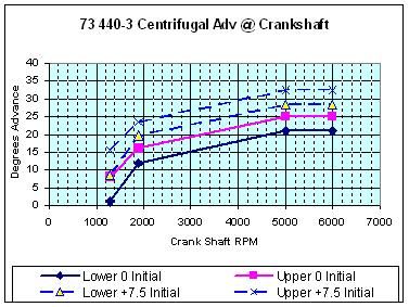 | ||
| Vacuum Advance | |||
| (Dist Degrees @ Inches of Mercury) 1.0º to 4.0º @ 10.5" 8.0º to 10.5º @ 15.5" | Crankshaft Degrees @ Inches of Mercury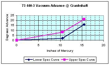 | ||
| 440-3 | 1974-1977 Electronic Distributor Reluctor Gap.008" Emissions Lable (7.5º ± 2.5º BTDC) BL-9Y Champion - .035" Gap Firing Order 1-8-4-3-6-5-7-2 | Centrifugal Advance | |
| (Dist Degrees @ Dist RPM) 0.5º to 4.0º @ 650 RPM 6.0º to 8.0º @ 950 RPM 10.5º to 12.5º @ 2500 RPM | Crankshaft Degrees @ Crankshaft RPM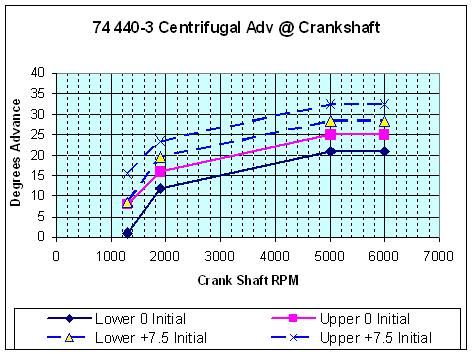 | ||
| Vacuum Advance | |||
| (Dist Degrees @ Inches of Mercury) 1.0º to 4.0º @ 10.5" 8.0º to 10.5º @ 15.5" | Crankshaft Degrees @ Inches of Mercury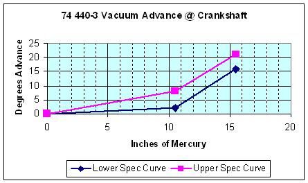 | ||
</BODY>
</HTML>
Post by: rcaircraftnut on January 08, 2011, 09:48 PM
Post by: intofire1 on January 13, 2011, 06:34 PM
Just got to say "Thank You". This is great, I can even understand it, and I am not a mechanic. You put allot of work into it and I Thank you.
Gil in LA
Post by: DaveVA78Chieftain on January 13, 2011, 07:24 PM
Dave
Post by: DaveVA78Chieftain on March 29, 2011, 08:45 AM
If you are saying that the engine would start after you performed steps 9 and 10 then I would say it's one of the following:
1) Intermittant wire connection
2) Intermittant open in the coil
3) Electronic components in the ignition module breaking down.
4) Ballast rsistor has an intermittant open once it is heated up. It can get to hot to touch.
No telling how old the coil is. The only real enemies of the electronic stuff is cold/heat shock and vibration. Over the years they do break down, sometimes in slow odd ways. It would be better to just replace the coil, ignition module and ballast resistor. Would not be the first time someone here came across a odd problem with either one of those devices. Think of it as a 35 year tune-up.
Most of the checks in the procedure are simply to verify that voltage is getting to each device. The characteristics of a device can change during actual operation. Most all of us have had a electronic device that when initially turned on it works fine. After warming up it starts having problems. The components here can exhibit the same type of problems.
Dave
Post by: LJ-TJ on March 29, 2011, 09:05 AM
Post by: scarecrovv on March 29, 2011, 07:26 PM
Post by: intofire1 on March 29, 2011, 10:16 PM
Ok time to go to NAPA and spend a little money to replace the coil, ignition module, Rotor & Cap, plugs & wires and ballast resistor.
Thanks for all the info. the wife is out of town working and what better way to spend the weekend. It's cheaper than going to a bar. Gil Los Angeles
Post by: DaveVA78Chieftain on March 29, 2011, 11:42 PM
Spring Tune up :D
Dave
Post by: JCMAC on March 24, 2015, 07:23 PM
Do you have a pic of the timing tab for the 413-1 engine? My tab is so painted over I can't determine for sure what the three marks are.
Thanks,
John
Post by: JCMAC on March 24, 2015, 07:42 PM
Look at the graphs for 1972 423-2 distributor curves.
On the centrifugal advance: it says 12° to 14° @ 2000 dist or 4000 engine RPM - now look at the graph. It is showing 24-33° for 4,000 RPM ??
On the Vacuum Advance there is a similar mismatch in that is says 8.5° to 11.5° @ 12" of vac. BUT the graph shows 17-23° at 12 " of vac ??
Comments
John
PS: My RV Dyno shop has me running 10° idle, 20° of centrifugal advance and 18° of vacuum - runs great and no knocking (rebuilt 413-1 engine).
Post by: DaveVA78Chieftain on March 24, 2015, 10:34 PM
The distributor rotates 1 revolution for every 2 revolutions of the crankshaft so,
12° rotation of the distributor is 24° rotation of the crankshaft.
12° to 14° advance measured at the distributor = 24° to 28° measured at the crankshaft.
The solid lines represent the curve with an initial advance of 0°
The dotted lines represent the curve with an initial advance of +5°
You stated:
10° advanced initial (at idle) with 20° centrifugal advance which provides a total of 30° max centrifugal
Add in 18° max vacuum advance you have a maximum advance of 48° total.
Given the values, that is all in reference to the crankshaft.
If I converted that to be referenced to the distributor:
5° advanced initial (at idle) with 10° centrifugal advance which provides a total of 15° max centrifugal
Add in 9° max vacuum advance you have a maximum advance of 24° total.
Dave
Post by: JCMAC on March 25, 2015, 01:27 PM
Do you have a pic of the timing tab for the 413-1 engine? My tab is so painted over I can't determine for sure what the three marks are.
Thanks,
John
Post by: DaveVA78Chieftain on March 25, 2015, 06:55 PM
(https://www.classicwinnebagos.com/forum/proxy.php?request=http%3A%2F%2Fstore.440source.com%2Fimages%2F1001063.jpg&hash=ec689d939704ea78b3ac2bc27d2fc51f8aba2a8f)
May the camping bug bite ya hard :)ThmbUp Dave
Post by: JCMAC on March 25, 2015, 08:01 PM
Thanks for the primer, I forgot to double the degrees Hm?
Anyway, using the chart, at 4,000 rpm (crank) and 7° initial/idle advance the chart shows 30-35° of Mechanical Advance. Now we add about 22° of vacuum advance for a Total Advance of 52°-57° which is like a max performance spec. www.imperialclub.com/repair/electrical/electronic
page 6.
Comments?
John
Post by: DaveVA78Chieftain on March 25, 2015, 09:29 PM
Lower spec @ 12" vacuum: 48.5° = 7.5° (initial) + 24° (mechanical) + 17° (Vacuum)
Upper spec @ 12" vacuum: 58.5° = 7.5° (initial) + 28° (mechanical) + 23° (Vacuum)
Total advance @ 12" vacuum should be between 48.5° and 58.5°.
The "tricks" come in by the rate (how fast) which the mechanical curve comes in for the needs of the given application (family sedan vs race engine). Controlled by the centrifugal advance weights and springs.
Remember race (heavy foot) basically = 0-3" vacuum. Eliminate the vacuum advance value from total when you push your foot to the floor. Going up hills is like race mode (low vacuum). Power circuit in carburetor (richer mixture) kicks in between 0 to 6" vacuum. Low vacuum is the engine saying I need richer fuel mix and lower total advance to prevent premature combustion (ping).
Straight line level road with easy foot pressure (gas savor mode) = max vacuum. usually around 10" to 12" vacuum irregardless if using manifold or ported vacuum source. Thats why many people use a vacuum gauge to help maintain maximum fuel economy.
Lower octane gas can = ping (cylinder fires to early) which means lower initial advance is required to prevent ping.
The 56° max total advance value on that web page is intended to prevent damage to the engine due to premature combustion. If you look around, you will find a range of 50° to 58° is typical the recommended area for all V8 engines.
Dave
Post by: cosmic on March 25, 2015, 10:00 PM
Post by: JCMAC on March 26, 2015, 04:24 PM
Thank you for the help. :)ThmbUp
John
Post by: Srmartinez1027 on June 04, 2015, 12:23 AM
Post by: patriklprice on June 21, 2015, 12:25 PM
Post by: DaveVA78Chieftain on June 22, 2015, 09:21 PM
Post by: patriklprice on June 24, 2015, 02:02 PM
I bought the electronic conversion which includes the distributor, coil,
0.5 ohm single resister & ECU. Do I now just discard the old 4 prong ballast or do I still need the 5 ohm side?
Question 2
I still have the single field alternator & wanting b to change to the newer style that has 2 FLD Taps. If I change the alternator which has a built in voltage regulator, can I then remove the old voltage regulator by the ecu?
I have the 1977 Winnebago Chieftain that someone put a 400 engine in.
Post by: DaveVA78Chieftain on June 25, 2015, 07:15 PM
Dave
Post by: patriklprice on June 25, 2015, 07:38 PM
The new 5 ohm 4 prong combination & 1.5 ohm ballast resistor is mounted on just the 1.5 ohm side. The 5 ohm side I didnt hook up at all. Ive looked at several different schematics but their all confusing & show different ways to wire this circuit. Your above illustration confuses me because that ecu has 5 pins where as mine is a 4 pins so the 5th pin throws me off
Ready to pull my hair out.
Post by: patriklprice on June 25, 2015, 07:49 PM
The tow company wanted $185 just to take it 6 miles so if I can get it running with just the $30 I've got in it then I've saved $170.
Post by: DaveVA78Chieftain on June 25, 2015, 08:35 PM
Post by: DaveVA78Chieftain on June 25, 2015, 08:44 PM
I take it you purchased MOPAR kit # P3690427 off Amazon for the 361-383-400 B Engines. Here is the manual for that kit: http://www.mymopar.com/downloads/elecignconv.pdf (http://www.mymopar.com/downloads/elecignconv.pdf). That has a 5 pin ECM.
Post by: patriklprice on June 27, 2015, 12:57 PM
# 0030M08. It's shiny in color with a gold heat sink but went bad after the wire burned up. I later got an autozone 4 pin ecm made by Duralast part number CR109. It works off a 1.5 ohn resister but engine still backfires.
the Proffesional ecm kit I got from Amazon has not arrived yet.
what a mess!
Post by: patriklprice on June 27, 2015, 01:19 PM
I bought some wire, flex tubing & fittings to reinstall the alternator wire back to the voltage regulator. No wonder why the guy told me to disconnect the battery every night.
It's all worth it I guess considering the RV was free.